
Page 41 - 《橡塑技术与装备》英文版2025年12月
P. 41
PROCESS AND EQUIPMENTS
to potentially overcome short-term overload.
1—Crankshaft; 2—Reduction gearbox; 3—Flywheel; 4—Motor;
5—Upper tool post; 6—C-type side arm
Figure 1 Schematic diagram of the cutting mechanism
2 Transmission mechanism of reduction
gearbox
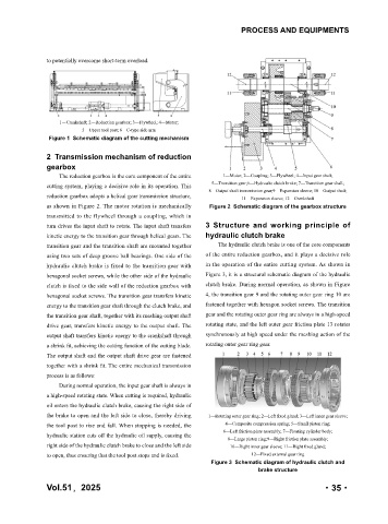
The reduction gearbox is the core component of the entire 1—Motor; 2—Coupling; 3—Flywheel; 4—Input gear shaft;
cutting system, playing a decisive role in its operation. This 5—Transition gear;6—Hydraulic clutch brake; 7—Transition gear shaft;
8—Output shaft transmission gear;9—Expansion sleeve; 10—Output shaft;
reduction gearbox adopts a helical gear transmission structure, 11—Expansion sleeve; 12—Crankshaft
as shown in Figure 2. The motor rotation is mechanically Figure 2 Schematic diagram of the gearbox structure
transmitted to the flywheel through a coupling, which in
turn drives the input shaft to rotate. The input shaft transfers 3 Structure and working principle of
kinetic energy to the transition gear through helical gears. The hydraulic clutch brake
transition gear and the transition shaft are mounted together The hydraulic clutch brake is one of the core components
using two sets of deep groove ball bearings. One side of the of the entire reduction gearbox, and it plays a decisive role
hydraulic clutch brake is fixed to the transition gear with in the operation of the entire cutting system. As shown in
hexagonal socket screws, while the other side of the hydraulic Figure 3, it is a structural schematic diagram of the hydraulic
clutch is fixed to the side wall of the reduction gearbox with clutch brake. During normal operation, as shown in Figure
hexagonal socket screws. The transition gear transfers kinetic 4, the transition gear 9 and the rotating outer gear ring 10 are
energy to the transition gear shaft through the clutch brake, and fastened together with hexagon socket screws. The transition
the transition gear shaft, together with its meshing output shaft gear and the rotating outer gear ring are always in a high-speed
drive gear, transfers kinetic energy to the output shaft. The rotating state, and the left outer gear friction plate 13 rotates
output shaft transfers kinetic energy to the crankshaft through synchronously at high speed under the meshing action of the
a shrink fit, achieving the cutting function of the cutting blade. rotating outer gear ring gear.
The output shaft and the output shaft drive gear are fastened
together with a shrink fit. The entire mechanical transmission
process is as follows:
During normal operation, the input gear shaft is always in
a high-speed rotating state. When cutting is required, hydraulic
oil enters the hydraulic clutch brake, causing the right side of
the brake to open and the left side to close, thereby driving 1—Rotating outer gear ring; 2—Left fixed gland; 3—Left inner gear sleeve;
the tool post to rise and fall. When stopping is needed, the 4—Composite compression spring; 5—Small piston ring;
6—Left friction plate assembly; 7—Floating cylinder body;
hydraulic station cuts off the hydraulic oil supply, causing the
8—Large piston ring;9—Right friction plate assembly;
right side of the hydraulic clutch brake to close and the left side 10—Right inner gear sleeve; 11—Right fixed gland;
to open, thus ensuring that the tool post stops and is fixed. 12—Fixed external gear ring
Figure 3 Schematic diagram of hydraulic clutch and
brake structure
Vol.51,2025 ·35·