
Page 45 - 《橡塑技术与装备》英文版2025年12月
P. 45
PROCESS AND EQUIPMENTS
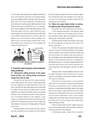
to 4.0~4.5 MPa, rotate the handle on the inflation and detection between the gearbox output shaft and the crankshaft, readjust
device counterclockwise, slowly open the accumulator inflation the circumferential angle of the crankshaft on the other end,
screw, and gradually inflate the nitrogen. When the pressure and restore the circumferential consistency between the left
gauge reaches 30% of the rated pressure, the inflation speed and right ends of the crankshaft.
can be increased to reach the required inflation pressure. Do not 5.2 When the upper blade holder is cutting,
inflate the gas into the accumulator all at once to avoid rupture it suddenly falls off and cannot be raised
due to uneven expansion of the airbag during inflation. When The possible reasons for this phenomenon are as follows:
the pressure gauge reaches the required inflation pressure, (1) The internal friction plate of the hydraulic clutch
close the handle on the nitrogen cylinder, then rotate the handle brake is worn, leading to an increased gap between the inner
of the inflation and detection device clockwise, tighten the and outer friction plates, which in turn reduces the overall
inflation screw on the accumulator, open the deflation valve braking torque of the hydraulic clutch brake.
handle (at B) to relieve the pressure inside the tube, remove Treatment method: Replace the hydraulic clutch brake
the special tool, screw on the top cover of the accumulator, and as a whole or replace the inner and outer friction plates of the
complete the inflation process. hydraulic clutch brake.
(2) Wear of the gear pump in the hydraulic system causes
a decrease in pressure or pressure fluctuations in the hydraulic
system, resulting in reduced friction between the inner and
outer friction plates of the calender clutch, and a decrease in
the overall braking torque of the hydraulic clutch brake. In this
situation, a typical phenomenon occurs: the oil temperature in
Figure 7 Schematic diagram of nitrogen charging for the hydraulic system rises, and the gear pump housing feels hot
accumulator to the touch. When measured with an infrared thermometer, the
surface temperature of the gear pump is expected to be above
5 Common fault analysis and troublesho 50℃.
oting methods Treatment method: Clean the hydraulic system oil circuit
5.1 During the cutting process of the upper thoroughly and replace it with new hydraulic oil and gear
blade holder, the cutting blade wallboard pump. To avoid damage to the gear pump, regularly replace the
sways from side to side filter of the oil circuit system.
During the normal operation of the cutting mechanism
(3) Insufficient nitrogen pressure in the accumulator
of the cutting machine, there may be a phenomenon where
leads to the loss of its function in compensating and stabilizing
the entire wallboard of the upper blade holder swings from the pressure of the hydraulic system, resulting in pressure
side to side while the upper blade holder moves up and down
reduction or pressure fluctuations during cutting by the cutting
for cutting. The main reason for this phenomenon is that the
blade. In this situation, a typical phenomenon occurs: during
crankshaft is not aligned horizontally, resulting in an angular cutting by the cutting blade, the pressure in the hydraulic
difference in the circumferential direction. During operation,
system fluctuates significantly, with the pressure rapidly
due to the dynamic imbalance of the crankshaft, overall
dropping with each cut and quickly returning to normal when
vibration is generated and transmitted to the wallboard of the
the cutting stops. The pressure gauge needle swings widely
blade holder. Prolonged operation may cause the C-shaped side within a short period of time.
wall to fracture or other parts to be damaged due to long-term
Treatment method: Utilize the FPU-1 inflation and testing
uneven stress.
device to measure the pressure of the accumulator, and then re-
Handling method: Utilize professional tools, with one inflate the accumulator with nitrogen gas.
end of the crankshaft as the benchmark, loosen the shrink fit
(4) The hydraulic system's overflow valve or accumulator
Vol.51,2025 ·39·