
Page 42 - 《橡塑技术与装备》英文版2025年12月
P. 42
HINA R&P TECHNOLOGY AND EQUIPMENT
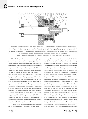
1—Round nut; 2—Cylindrical roller bearing; 3—Gear shaft; 4—Locating sleeve A; 5—Locating sleeve B; 6—Deep groove ball bearing; 7—Locating sleeve C;
8—Hexagon socket screw; 9—Transition gear; 10—Rotating outer gear ring; 11—Left fixed gland; 12—Left inner gear sleeve; 13—Left outer gear friction plate;
14—Left inner gear friction plate; 15—Composite compression spring; 16—Floating cylinder; 17—Small piston ring; 18—Right outer gear friction plate;
19—Right inner gear friction plate; 20—Large piston ring; 21—Fixed outer gear sleeve; 22—Right inner gear sleeve; 23—Right fixed gland; 24—Locating sleeve D;
25—Cylindrical roller bearing; 26—Locating sleeve E; 27—Round nut; 28—Retaining washer; 29—Rotating joint
Figure 4 Schematic diagram of transmission through the transition gear shaft of the reducer
When the C-type side arm cutter is stationary, the gear floating cylinder 16 through the rotary joint 29. The floating
shaft 3 remains stationary. The transition gear 9 and the cylinder is located within a sealed cavity formed by the large
rotating outer gear ring are fastened together using hexagonal piston ring 20, small piston ring 17, and right inner gear sleeve
socket screws. The transition gear and the rotating outer gear 22. Under the action of high-pressure hydraulic oil, the floating
ring are always in a high-speed rotating state. The left outer cylinder is pushed to move leftward against the pressure of the
gear friction plate rotates synchronously at high speed under combined compression spring 15, compressing the left inner
the meshing action of the rotating outer gear ring gear. The gear friction plate 14 and the left outer gear friction plate 13
fixed outer gear sleeve is fixed to the reducer housing using together. The inner and outer gear friction plates generate a
hexagonal socket screws. The right outer gear friction plate large frictional force under external force. With the mutual
18 remains stationary under the meshing action of the fixed engagement of the inner and outer gears, components such
outer gear sleeve gear. The floating cylinder 16 moves to the as the left inner gear sleeve 12, left fixed gland 11, left outer
right under the action of the combined compression spring 15, gear friction plate, left inner gear friction plate, and combined
compressing the right inner gear friction plate 19 and the right compression spring maintain a consistent state. At the same
outer gear friction plate. The inner and outer gear friction plates time, after the right outer gear friction plate and right inner
generate a large friction force under external force, maintaining lining friction plate lose external force, gaps are formed
a stationary state. The right inner gear sleeve 22 is keyed to between the friction plates, which are then in a free state.
the gear shaft 3. The right inner gear sleeve and the right inner The transition gear drives the gear shaft to rotate as a whole
gear friction plate keep the gear shaft 3 stationary under the under the transmission of the upper meshing gear, thereby
meshing action of the gears, thus ensuring that the C-type side transmitting kinetic energy to the C-type side arm and driving
arm cutter can be stationary at the required position. the upper blade frame to move up and down linearly for
When the C-type side arm cutting blade needs to perform material cutting. When the cutting action is completed and the
cutting, high-pressure hydraulic oil enters the right side of the upper blade frame moves to the highest position, an external
·36· Vol.51,No.12