
Page 46 - 《橡塑技术与装备》英文版2025年12月
P. 46
HINA R&P TECHNOLOGY AND EQUIPMENT
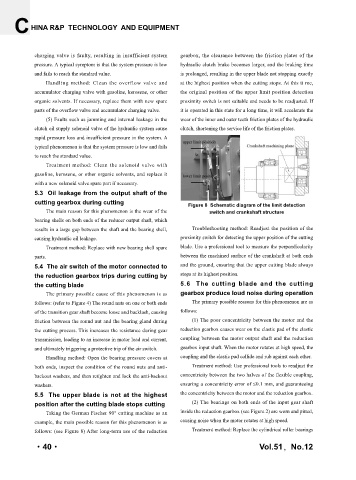
charging valve is faulty, resulting in insufficient system gearbox, the clearance between the friction plates of the
pressure. A typical symptom is that the system pressure is low hydraulic clutch brake becomes larger, and the braking time
and fails to reach the standard value. is prolonged, resulting in the upper blade not stopping exactly
Handling method: Clean the overflow valve and at the highest position when the cutting stops. At this ti me,
accumulator charging valve with gasoline, kerosene, or other the original position of the upper limit position detection
organic solvents. If necessary, replace them with new spare proximity switch is not suitable and needs to be readjusted. If
parts of the overflow valve and accumulator charging valve. it is operated in this state for a long time, it will accelerate the
(5) Faults such as jamming and internal leakage in the wear of the inner and outer teeth friction plates of the hydraulic
clutch oil supply solenoid valve of the hydraulic system cause clutch, shortening the service life of the friction plates.
rapid pressure loss and insufficient pressure in the system. A
typical phenomenon is that the system pressure is low and fails
to reach the standard value.
Treatment method: Clean the solenoid valve with
gasoline, kerosene, or other organic solvents, and replace it
with a new solenoid valve spare part if necessary.
5.3 Oil leakage from the output shaft of the
cutting gearbox during cutting Figure 8 Schematic diagram of the limit detection
The main reason for this phenomenon is the wear of the switch and crankshaft structure
bearing shells on both ends of the reducer output shaft, which
results in a large gap between the shaft and the bearing shell, Troubleshooting method: Readjust the position of the
causing hydraulic oil leakage. proximity switch for detecting the upper position of the cutting
Treatment method: Replace with new bearing shell spare blade. Use a professional tool to measure the perpendicularity
parts. between the machined surface of the crankshaft at both ends
5.4 The air switch of the motor connected to and the ground, ensuring that the upper cutting blade always
the reduction gearbox trips during cutting by stops at its highest position.
the cutting blade 5.6 The cutting blade and the cutting
The primary possible cause of this phenomenon is as gearbox produce loud noise during operation
follows: (refer to Figure 4) The round nuts on one or both ends The primary possible reasons for this phenomenon are as
of the transition gear shaft become loose and backlash, causing follows:
friction between the round nut and the bearing gland during (1) The poor concentricity between the motor and the
the cutting process. This increases the resistance during gear reduction gearbox causes wear on the elastic pad of the elastic
transmission, leading to an increase in motor load and current, coupling between the motor output shaft and the reduction
and ultimately triggering a protective trip of the air switch. gearbox input shaft. When the motor rotates at high speed, the
Handling method: Open the bearing pressure covers at coupling and the elastic pad collide and rub against each other.
both ends, inspect the condition of the round nuts and anti- Treatment method: Use professional tools to readjust the
backout washers, and then retighten and lock the anti-backout concentricity between the two halves of the flexible coupling,
washers. ensuring a concentricity error of ≤0.1 mm, and guaranteeing
5.5 The upper blade is not at the highest the concentricity between the motor and the reduction gearbox.
position after the cutting blade stops cutting (2) The bearings on both ends of the input gear shaft
Taking the German Fischer 90° cutting machine as an inside the reduction gearbox (see Figure 2) are worn and pitted,
example, the main possible reason for this phenomenon is as causing noise when the motor rotates at high speed.
follows: (see Figure 8) After long-term use of the reduction Treatment method: Replace the cylindrical roller bearings
·40· Vol.51,No.12