
Page 36 - 《橡塑技术与装备》英文版2025年12月
P. 36
HINA R&P TECHNOLOGY AND EQUIPMENT
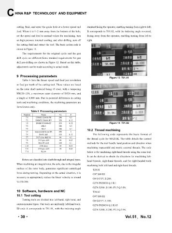
cutting fluid, and enter the guide hole at a lower speed and standard facing the operator, enabling turning from right to left;
feed. When it is 1~2 mm away from the bottom of the hole, B corresponds to T01.02, with the indexing angle reversed,
set the speed and feed to normal values for machining, turn facing away from the operator, enabling turning from left to
on high-pressure internal cooling, and after drilling, turn off right.
the cutting fluid and retract the tool. The basic action code is
shown in Figure 11.
The requirements for the original cycle and the gun
drill cycle are different.Some standard requirements for gun
drill pre-drilling are shown in Figure 12. Based on this table,
adjustments can be made according to actual needs.
9 Processing parameters Figure 13 T01.01
Table 6 lists the linear speed and feed per revolution
or feed per tooth of the cutting tool. These values are based
on the rotor shaft material being 45 steel, with a tempering
HB220~250, a maximum outer diameter of D520 mm, and
a length of 4,000 mm. Due to potential differences in cutting
tools and machining conditions, the machining parameters are
for reference only.
Table 6 Processing parameters
Number Name Vc F
T1 CNMG120408-PR 200 0.3
T2 DNMX150608-WF 250 0.12
T2 DNMG150608-PP 250 0.12 Figure 14 T01.02
T3 6R0.2 100 0.3
T4 R2.5 100 0.1 10.2 Thread machining
T5 trapezoidal thread P6 100 6
T6 D60U drill 150 0.15 The following code represents the basic format of
T7 D15 alloy drill bit 80 0.1 the thread cycle for MAZAK. The table details the control
T8 D15 gun drill 80 0.05
T9 D24.5U drill 120 0.1 methods for the tool handle hand position and direction when
T10 D10 alloy 50 0.05 machining trapezoidal and metric external threads. The code
T11 D10 gun drill 50 0.05
T12 Rc3/4 below is for machining right-hand threads using the same tool.
It can be derived to obtain the directions for machining left-
Rotors are classified into shaft-through and integral types. hand threads, right-hand threads, and for right-handed tools
When machining an integral rotor, the axle, due to the irregular machining both left-hand and right-hand threads.
surface of the rotor body, generates significant centrifugal
T28.01
force during turning. Depending on the actual situation, it is G97 S80 R1
necessary to appropriately reduce the linear velocity to around G0 G43 P1 Z-200.
Vc150-200.
G276 P020030 Q.1 R.1
G276 X300. Z-100. P3.5 Q.3 F6.
10 Software, hardware and NC T28.02
10.1 Tool setting G97 S80 R1
Turning tools are divided into left-hand, right-hand, and G0 G43 P1 Z-100.
center-mounted types. Our tools are uniformly left-hand tools. G276 P020030 Q.1 R.05
ID code A corresponds to T01.01, with the indexing angle G276 X300. Z-200. P3.5 Q.3 F6.
51
12
·30· Vol.51,No.12
·30·
期
第
卷 第