
Page 37 - 《橡塑技术与装备》英文版2025年12月
P. 37
MACHINERY AND MOLD
Table 7 Threads (1) In CAM software such as ESPRIT, for settings with
Knife handle grip Direction Dextro-R Levo-L precision dimension requirements, use the mid-range value.
left T28.01 > → > ←
left T28.02 > ← > → For those without precision dimensions, set it to 0.
Trapezoidal Thread Metric Thread (2) During the actual machining process, dimensions
Thread Pitch F Thread Depth P Thread Pitch F Thread Depth P
4 2.25 2 1.3 without tolerance and with lower requirements are taken.
5 2.75 3 1.95 After machining, the dimensions are measured, and the value
6 3.5
Trapezoidal thread: thread depth P=0.5F+ac; obtained by subtracting the measured dimensions from the
P=1.5~5ac=0.25; P=6~12 ac=0.5; P=14~44 ac=1 programmed dimensions is compensated within the machine
Metric thread: thread depth P=0.65F. tool. If there are precision requirements for the trial cutting
10.3 Cooling system part, the CNC program should be modified or the trial cutting
High-pressure cooling involves increasing the pressure should be performed after compensation within the machine
of the cutting fluid to a specific level, allowing it to precisely tool. After the trial cutting, wear compensation should be
reach the cutting area through internal cutting fluid channels performed, as shown in Figure 15.
for rapid cooling. The use of high-pressure cooling for turning (3) After processing the two ends, before processing the
tools, U-drills, and gun drills can achieve good results, as middle section, change the cutting blade and repeat the second
shown in Table 8. Of course, tool materials such as ceramic step.
milling cutters and CBN are not suitable for using cutting fluid.
(1) In terms of cooling effect, high-pressure cooling
technology involves precisely and quantitatively spraying
coolant directly onto the cutting area of the blade using high
pressure, thereby maximally removing heat from the cutting
area and achieving rapid cooling.
(2) In terms of chip control ability, high-pressure cooling Figure 15 Compensation Settings
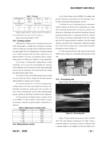
not only effectively reduces cutting heat but also increases 10.5 Processing site
cutting brittleness, making it easier to break.
Figure 16 shows the GE1000T at the processing site.
(3) From the perspective of tool life, high-pressure
cooling reduces tool wear and extends tool service life.
Generally, increasing the cutting speed will exacerbate tool
wear, but by increasing the feed rate after applying high-
pressure cooling, the shortening of tool life is not as significant.
(4) The pressure for high-pressure cooling can be
set in ESPRIT. Use M131 M100 or M131 K650 to control
the pressure. Generally, using the middle section M103 is
sufficient.
Table 8 High-pressure cooling control
User-defined M code
< 400 M100
< 500 M101 Figure 16 Processing site
< 700 M102
< 800 M103
< 900 M104 Figure 17 shows partial measurements of the GE1000T
< 1 000 M105 shaft. The outer diameter dimensions are stable. Using a
≥ 1 000 M106
10.4 Dimensional control handheld roughness measuring instrument calibrated with
a standard template, the roughness of the rotor shaft can be
年,2025
Vol.51 51 卷 ·31·
·31·
2025 第