
Page 43 - 《橡塑技术与装备》英文版2025年12月
P. 43
PROCESS AND EQUIPMENTS
switch detects the signal, and the electrical system transmits
a stop command to the hydraulic system. The hydraulic oil
stops supplying, and the floating cylinder in the hydraulic
clutch brake moves rightward under the action of the combined
compression spring, locking the gear shaft. The C-type side
arm stops moving and remains in a stationary state.
4 Operating principle of hydraulic system
and accumulator
4.1 Operating principle of hydraulic system
Generally, hydraulic system designs vary slightly among
equipment from different manufacturers. This article takes the
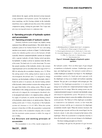
hydraulic system of the German Fischer 90° steel cord cutting 1—Reduction gearbox; 2—Hydraulic clutch brake; 3—Accumulator;
4—Hand valve; 5—Pressure gauge; 6—Pressure switch;
machine as an example, as shown in Figure 5. In this hydraulic
7—Electromagnetic directional valve; 8—Relief valve; 9—Check valve;
system, the reduction gearbox serves as the hydraulic oil tank 10—Accumulator charging valve; 11—Check valve; 12—Pressure switch;
(typically, domestic equipment hydraulic systems are designed 13—Filter; 14—Check valve; 15—Hydraulic pump;
16—Hydraulic pump motor
with a separate hydraulic oil tank). During normal operation,
Figure 5 Schematic diagram of hydraulic system
the hydraulic oil pump is always in operation under the drive operation
of the motor. The hand valve 4 is in the closed state. To ensure
the normal operation of the hydraulic clutch 2, the system's the hydraulic system. There are three types of gas-charged
required pressure can be controlled within the range of 4.0~6.5 accumulators in hydraulic systems: bladder-type, piston-
MPa by adjusting the accumulator charging valve 10. When type, and diaphragm-type. The hydraulic system utilizes a
the cutting system of the cutting machine needs to cut, the welded diaphragm accumulator (see Figure 6). The diaphragm
electromagnetic directional valve 7 is energized to change accumulator consists of a liquid part and a gas part, with
direction, and the hydraulic oil flows to the hydraulic clutch 2. the diaphragm serving as an airtight and medium-separating
Under the action of oil pressure, the internal floating cylinder element. The gas part is pre-charged with nitrogen gas. The
of the hydraulic clutch switches to achieve the cutting action of function of the diaphragm accumulator is to convert the
the upper blade holder of the cutting system. When the upper energy in the system into compressed potential energy at the
blade holder of the cutting system rises to the highest position appropriate time for storage. When the cutting system cuts, the
and needs to be stopped, the electromagnetic directional valve compressed potential energy is converted into hydraulic energy
is de-energized and returns to its original position, cutting off and released to replenish the system. This process of energy
the supply of hydraulic oil, and the internal floating cylinder storage and release helps to ensure the stability of the hydraulic
of the hydraulic clutch returns to its initial position. When the system pressure. The fluid part of the diaphragm accumulator
cutting system cuts 2~3 times, the pressure of the hydraulic is connected to the hydraulic circuit, so that when the
system will decrease to 4.0~4.5 MPa. When the system pressure increases and the gas is compressed, the diaphragm
pressure is lower than 4.0 MPa, the accumulator is pressurized accumulator absorbs liquid. When the pressure decreases, the
under the action of the accumulator charging valve to ensure compressed gas expands and forces the stored liquid into the
that the maximum system pressure is within the range of hydraulic circuit. A valve plate is located at the bottom of the
6.0~6.5 MPa. diaphragm. When the accumulator is completely emptied, it
4.2 Structure and working principle of closes the hydraulic outlet to prevent damage to the diaphragm.
accumulator The basic working principle is as follows:
The accumulator is one of the crucial components of According to the gas law, the pressure of a gas increases
Vol.51,2025 ·37·