
Page 34 - 《橡塑技术与装备》英文版2025年12月
P. 34
HINA R&P TECHNOLOGY AND EQUIPMENT
Table 5 Work Step Design
Operation Step Content
First Clamping
OP1 One clamp and one support, clamp the small head and support the large head, with the coordinate system G54 on the right end face.
OP2 The maximum external diameter of the rough turning is D520.6, with a roughness of Ra1.6, and it is the position for the center frame.
OP3 Place the mobile center frame in the middle of D520.
OP4 Roughly machine the outer circumference of each part, with a radial allowance of 0.3 and an end face allowance of 0.1.
OP5 Fine-turn the outer circle and each part of the 1:12 conical surface, with a surface roughness of Ra1.6.
OP6 Fine turning of square groove and relief groove.
OP7 Dynamic precision turning of R6 circular arc groove.
OP8 The trapezoidal thread P6 of the vehicle, with both left-hand and right-hand threads.
OP9 Move the central frame to D380.
OP10 The maximum external diameter of the precision-turned part is D520.
OP11 Retreat to the original point M841.
OP12 Pre-drill a D15 bottom hole, with a pilot hole depth of 1.5D.
OP13 Gun drill D15 hole, depth 800 mm.
OP14 Drill a hole of D24.5.
OP15 Tap thread Rc3/4.
OP16 Spot face the D10 hole to ensure the guiding depth.
OP17 Gun drill D10 hole.
OP18 Roll back the top to M842.
OP19 Place the mobile center frame in the middle of D520.
OP20 Drill a water channel hole D60 with a depth of 250 mm.
OP21 Loosen the center frame.
OP22 Lifting, returning the top point to zero, and unloading the load.
Second Clamping
OP23 One clamp and one support, clamp the larger head and support the smaller head, with the coordinate system G54 on the right end face.
OP24 When measuring with a dial gauge, if the runout is less than 0.02, it is considered unqualified. Repair the top hole.
OP25 Move the central frame to D380.
OP26 Roughly machine the outer circumference of each part, with a radial allowance of 0.3 and an end face allowance of 0.1.
OP27 Vehicle retractable knife slot.
OP28 Fine machine all external circles, Ra1.6.
OP29 Thread M200×3.
OP30 Ladder drill, Rc3/4 bottom hole and D15 gun drill bottom hole.
OP31 Drill D15 hole.
OP32 Tap thread Rc3/4.
OP33 Spot face the D10 hole to ensure the guiding depth.
OP34 Gun drill D10 hole.
OP35 Drill a bottom hole from M10 to D8.5
OP36 Tap thread M10.
OP37 Loosen the center frame.
OP38 Lifting, returning the top point to zero, and unloading the load.
and whether moving from left to right or from right to left, the
iron chips flow towards the middle. They are prone to jumping
into the center frame rollers, causing damage to both the center
frame and the parts. To effectively solve this problem, a magnet
is used to attract the iron chips to the left and right surfaces of
the center frame.
8.3 OP4 rough turning
The radial allowance for rough turning is 0.3, and the end
face allowance is 0.1. It is not advisable to leave too much end
face allowance; 0.1 is more appropriate. Because we are using
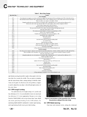
Sandvik CNMG120408, with an Ap of more than 3 mm, which Figure 8 Actual photo of the protection site, showing
can ensure good chip breaking. In the CAM software, the the precision milling of the rotor body.
machining depth should be optimized to ensure equal spacing, 8.4 OP5 finish turning
and rough turning should ensure good chip breaking. Fine-tune each external circle, setting the rotational
51
12
·28· Vol.51,No.12
·28·
期
第
卷 第