
Page 33 - 《橡塑技术与装备》英文版2025年12月
P. 33
MACHINERY AND MOLD
Table 4 lists the tool types required for each step, the processing content of each tool. Due to the vast amount of
custom names of the tools, and brief information about the brand information, specific brands are not mentioned.
Table 4 Tool for working steps
Number Type Name Remarks
T1 External cylindrical turning tool CNMG120408 rough turning
T2 External cylindrical turning tool DNMX150604 finish turning
T3 External circular groove cutter 6R0.2 Outer circular groove of the car
T4 External cylindrical slot cutter R2.5 Outer circular groove of the car
T5 Thread turning tool Trapezoidal thread P6 thread turning
T6 drilling D60U drill Drill a water hole
T7 drilling D15 alloy drill bit Pre-drilling
T8 drilling D15 gun drill Gun drill
T9 drilling D24.5U drill Drill the bottom hole
T10 End mill D10 alloy Pre-drilling and spot-facing
T11 drilling D10 gun drill Gun drill
T12 Thread cutter Rc3/4 tapping
T13 Thread turning tool M3 thread turning
T14 drilling Step drill bit drilling
T15 drilling D8.5 alloy drill bit drilling
T16 Tapping M10 tap Tapping
T17 Face milling cutter D63R6 Rough milling of keyway
T18 End mill D32 blade Corner clearance key slot
T19 End mill D20 alloy Fine milling of key slot
T20 drilling D20-60 degrees Repair the central hole
8 Process design
Table 5 lists the process sequence of each step in the
combined turning and milling finishing process, along with
a brief description of each procedure. From the design of
the entire process route, it can be seen that the combined
turning and milling process completes 90% of the machining
content in a single setup, which not only has high machining
efficiency but also effectively guarantees the accuracy of
various dimensions and positional shapes. This fully leverages
the advantages of combined turning and milling, allowing Figure 6 Installation
for flexible adjustments to the process and related process
resources according to actual needs. This article is for reference
only.
Next, we will conduct a simple process breakdown of
some issues that should be noted during certain procedures in
processing.
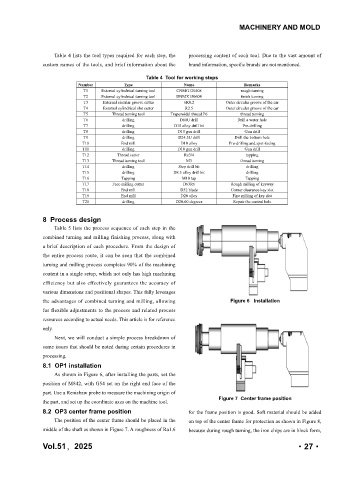
8.1 OP1 installation
As shown in Figure 6, after installing the parts, set the
position of M842, with G54 set on the right end face of the
part. Use a Renishaw probe to measure the machining origin of
Figure 7 Center frame position
the part, and set up the coordinate axes on the machine tool.
8.2 OP3 center frame position for the frame position is good. Soft material should be added
The position of the center frame should be placed in the on top of the center frame for protection as shown in Figure 8,
middle of the shaft as shown in Figure 7. A roughness of Ra1.6 because during rough turning, the iron chips are in block form,
年,2025
Vol.51 51 卷 ·27·
·27·
2025 第