
Page 100 - 《橡塑技术与装备》英文版2026年3期
P. 100
HINA R&P TECHNOLOGY AND EQUIPMENT
and has relatively long heating and cooling times. In order to save 3 Further introduction based on the
heating energy, reduce disassembly and assembly time, lighten the attached drawing of the overall structure
overall weight of the head, and save material costs. of the pipe extrusion head
3.1 A kind of extrusion pipe die utilizing a turbine-
2 Overall structure of extrusion die head driven biaxial orientation stretching device
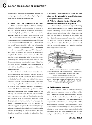
A kind of extrusion pipe head structure utilizing a As shown in Figure 1, an extrusion pipe head utilizing
turbine-driven dual-axis orientation stretching device, as shown a turbine-traction biaxial orientation stretching device mainly
in Figure 1, primarily comprises the following components: a comprises a head body connector, a splitter bracket, a head
head connecting body 1, a splitter bracket 2, a head body 3, a body, a turbine, a turbine handle, a die, and a pressure ring
turbine 4, a turbine handle 5, a die 9, and a pressure ring sleeve sleeve. The head connector, head body, die, and pressure ring
10. The interior of the head connecting body, head body, die, sleeve also include components such as a splitter cone, bolt,
and pressure ring sleeve is equipped with a cavity. Within the steel wire rope, output shaft, hollow core rod connecting
cavity, components such as a splitter cone 11, bolts 12, steel sleeve, hollow core rod transition sleeve, and hollow core rod,
wire ropes 17, an output shaft 6, a hollow core rod connecting which are connected in sequence. The main features of the
sleeve 13, a hollow core rod transition sleeve 15, and a hollow extrusion pipe head are as follows:
core rod 16 are arranged, forming a material flow channel. The
head connecting body and the head body are fixed together
using bolts. The other end of the head body is bolted to the
transition sleeve 8, and the other end of the transition sleeve 8
is threadedly fixed to the pressure ring sleeve at the end of the
die, thus constituting an internal cavity. One end of the splitter
cone within the cavity is equipped with a circular platform 14,
onto which the through-holes on the splitter ribs of the splitter
bracket are inserted. 1-Head body connector; 2-Diverter bracket; 3-Head body; 4-Turbine;
The output shaft of the turbine is inserted into the 5-Turbine handle; 6-Output shaft; 7-Turbine fixing plate; 8-Transition sleeve;
through-holes on the head connecting body and the splitter 9-Die nozzle; 10-Pressure ring sleeve; 14-Diverging cone; 12-Bolt;
13-Core rod connecting sleeve; 14-Circular cone;
ribs of the splitter bracket. Subsequently, the steel wire ropes 15-Hollow core rod transition sleeve; 16-Hollow core rod; 17-Steel wire rope.
are fixed using bolts. The splitter cone and the hollow core rod Figure 1 Schematic diagram of the overall structure of
connecting sleeve are threadedly fixed together, compressing the extrusion die head for the turbine-traction biaxial
orientation stretching device
and securing the splitter bracket. Its characteristics lie in the
following: a bolt is provided at one end of the output shaft 3.2 Turbine device structure
connected to the turbine between the splitter cone and the
As shown in Figures 2 and 3, the turbine device structure
hollow core rod connecting sleeve to fix and connect the steel
mainly consists of components such as the turbine 4, turbine
wire rope. The other end of the steel wire rope is connected
handle 5, output shaft 6, turbine fixing plate 7, bolt 12, and steel
to the orientation stretching device. The orientation stretching
wire rope 17. The interior of the turbine device is equipped
device is rotated by the turbine handle of the turbine, causing
with the turbine and output shaft. One side of the turbine is
the output shaft to wind and pull the steel wire rope, thus equipped with a turbine handle, and directly in front of the
moving the orientation stretching device back and forth. The
turbine is a turbine fixing plate. The said turbine fixing plate is
turbine fixing plate 7 is provided with connecting through-
equipped with a connecting through hole, through which the
holes, through which the threaded holes on the head connecting entire turbine device is connected and fixed with the threaded
body and the head body are connected, securing the turbine
hole provided on the head connecting body and head body. By
through the through-holes provided on the turbine fixing plate.
rotating the turbine handle, the turbine is driven to move the
·54· Vol.52,No.3