
Page 101 - 《橡塑技术与装备》英文版2026年3期
P. 101
PRODUCT AND DESIGN
steel wire rope fixed on the output shaft, which is then wound in Figure 4, and there are also designs where the diverter and
and pulled to move the orientation stretching device forward the bracket are integrated into a single structure, as shown in
and backward. When the orientation stretching device moves Figure 5. However, these structures are relatively bulky, time-
forward, the steel wire rope is loosened by rotating the turbine consuming and laborious to assemble and disassemble, and
handle, and under the friction force generated between the tube require relatively long heating and cooling times. In order to
blank and the orientation stretching device, the orientation save heating energy and assembly/disassembly time, reduce the
stretching device is driven to move forward. When the mass of the diverter cone, and accommodate the increased steel
orientation stretching device moves backward, the direction wire rope for storage, the diverter is designed to be hollow,
of rotation of the turbine handle is opposite to that of the steel as shown in Figure 6. A through hole is provided in the axial
wire rope loosening, causing the steel wire rope to tighten and diameter of the diverter cone's circular cone, and the output
drive the orientation stretching device to move backward. shaft of the turbine passes through the through hole provided
in the head connector and the diverter bracket 2's diverter rib.
The steel wire rope is then fixed with bolts. The outer diameter
of the diverter cone's circular cone is fitted into the inner hole
provided in the diverter cone bracket, and the diverter cone
is then connected to the hollow core rod through threads to
securely press the diverter bracket. The diverter 11 is designed
to be hollow, effectively storing the increased steel wire rope in
the hollow cavity, allowing the steel wire rope to smoothly pull
and guide the stretching device to move smoothly.
There are three main dimensions in the design of the
diverter here: the divergence angle α, the length L of the
diverging cone, and the radius R of the top fillet of the diverter,
(1)The selection of the diverter expansion angle α is
related to the viscosity of the plastic. For plastics with lower
Figure 2 Schematic diagram of turbine device structure
viscosity, the melt flow resistance is smaller, and α is usually
taken as 30°~60°; for plastics with higher viscosity, the melt
flow resistance is greater, and α is usually taken as 30°~45°.
(2) The length L of the diverging cone is calculated
according to the following formula:
L=(0.6-1.5)D 0
Where:
L—length of the diverging cone, mm;
D 0—Diameter at the outlet of the filter plate, mm.
Figure 3 Enlarged schematic diagram of bolt-fixed steel (3) The fillet radius (R) at the top of the diverter is
wire rope structure in direction A of the structure in generally taken as 0.5~2.0 mm.
figure 2
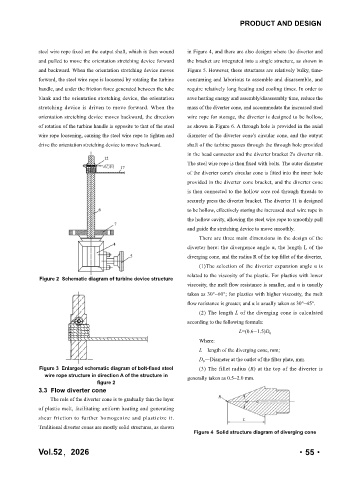
3.3 Flow diverter cone
The role of the diverter cone is to gradually thin the layer
of plastic melt, facilitating uniform heating and generating
shear friction to further homogenize and plasticize it.
Traditional diverter cones are mostly solid structures, as shown
Figure 4 Solid structure diagram of diverging cone
Vol.52,2026 ·55·