
Page 102 - 《橡塑技术与装备》英文版2026年3期
P. 102
HINA R&P TECHNOLOGY AND EQUIPMENT
turbine-traction dual-axis orientation stretching device involves
first cooling the extruded tube blank to room temperature
and then heating it to the stretching temperature. Specifically,
when the tube blank is pulled into the heating device by the
first traction machine for secondary heating, it is heated to a
highly elastic state, and then undergoes bidirectional stretching
Figure 5 Overall structural diagram of shunt and bracket design through an online production process using a movable
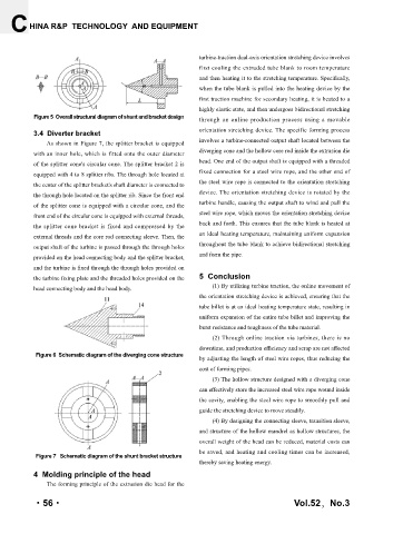
3.4 Diverter bracket orientation stretching device. The specific forming process
As shown in Figure 7, the splitter bracket is equipped involves a turbine-connected output shaft located between the
with an inner hole, which is fitted onto the outer diameter diverging cone and the hollow core rod inside the extrusion die
of the splitter cone's circular cone. The splitter bracket 2 is head. One end of the output shaft is equipped with a threaded
equipped with 4 to 8 splitter ribs. The through hole located at fixed connection for a steel wire rope, and the other end of
the center of the splitter bracket's shaft diameter is connected to the steel wire rope is connected to the orientation stretching
the through hole located on the splitter rib. Since the front end device. The orientation stretching device is rotated by the
turbine handle, causing the output shaft to wind and pull the
of the splitter cone is equipped with a circular cone, and the
front end of the circular cone is equipped with external threads, steel wire rope, which moves the orientation stretching device
the splitter cone bracket is fixed and compressed by the back and forth. This ensures that the tube blank is heated at
external threads and the core rod connecting sleeve. Then, the an ideal heating temperature, maintaining uniform expansion
output shaft of the turbine is passed through the through holes throughout the tube blank to achieve bidirectional stretching
provided on the head connecting body and the splitter bracket, and form the pipe.
and the turbine is fixed through the through holes provided on
the turbine fixing plate and the threaded holes provided on the 5 Conclusion
head connecting body and the head body. (1) By utilizing turbine traction, the online movement of
the orientation stretching device is achieved, ensuring that the
tube billet is at an ideal heating temperature state, resulting in
uniform expansion of the entire tube billet and improving the
burst resistance and toughness of the tube material.
(2) Through online traction via turbines, there is no
downtime, and production efficiency and scrap are not affected
Figure 6 Schematic diagram of the diverging cone structure
by adjusting the length of steel wire ropes, thus reducing the
cost of forming pipes.
(3) The hollow structure designed with a diverging cone
can effectively store the increased steel wire rope wound inside
the cavity, enabling the steel wire rope to smoothly pull and
guide the stretching device to move steadily.
(4) By designing the connecting sleeve, transition sleeve,
and structure of the hollow mandrel as hollow structures, the
overall weight of the head can be reduced, material costs can
be saved, and heating and cooling times can be increased,
Figure 7 Schematic diagram of the shunt bracket structure
thereby saving heating energy.
4 Molding principle of the head
The forming principle of the extrusion die head for the
·56· Vol.52,No.3