
Page 75 - 《橡塑技术与装备》英文版2026年3期
P. 75
MACHINERY AND MOLD
wire core and an outer wrapped wire. The bead wire core is the first layer, closely adhering to the circumferential surface
slightly thicker and forms a cylindrical ring after butt welding. of the first layer of wire, and is fully filled in adjacent order
Depending on different specifications, the outer wrapped wire to complete the second layer of winding. Similarly, the third,
is divided into multiple layers. The first layer of wire is closely fourth, and subsequent layers are wound in this manner. As
arranged adjacent to the bead wire core until the layer is fully shown in figure 1:
filled. The second layer is wound in the opposite direction to
Figure 1 Schematic diagram of circular steel wire ring arrangement
1.2 Winding parameters for circular cross-
section steel wire rings
The selection of bead wire winding parameters mainly
includes: bead wire core diameter, outer winding wire diameter,
winding lead number, winding layer number, number of wires
per layer, winding angle, etc. The selection results can form
different specifications and different wire arrangement patterns
of circular bead wires.
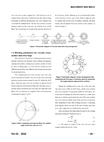
The winding process of the circular steel wire ring
can be described as follows: the core of the steel wire ring Figure 3 Schematic diagram of wire arrangement after
completing the first layer of winding, where β represents
performs circular motion around its axis OZ within the XOY
the angle between adjacent wire sections
plane, while the outer steel wire performs reciprocal curved
motion along the axial direction of the steel wire ring core (i.e., During the winding process, the core of the steel wire
circular motion around the steel wire ring core within the XOZ ring rotates once within the XOY plane, and the outer winding
plane). The two motions are coupled to form a helical motion, steel wire completes N lead spirals within the XOZ plane. For
as illustrated in figures 2 and 3. every lead of winding, the steel wire rotates by a little more
than one revolution, ensuring that the end of the outer winding
steel wire connects with the head of the steel wire in that layer
after completing N leads. After winding one layer, a connecting
point appears where the ends of the outer winding steel wire
meet, and a copper sleeve is installed for connection.
After calculation, the relationship formula for the winding
parameters during the winding process is:
360°
α= (1)
N
360°
θ=360°+ (2)
M . N
Figure 2 After completing one lead winding, the rotation α—The angle of rotation of the wire coil core when
angle of the wire coil core is α
wrapped with steel wire for 1 lead;
Vol.52,2026 ·29·