
Page 68 - 《橡塑技术与装备》英文版2026年1月
P. 68
HINA R&P TECHNOLOGY AND EQUIPMENT
entire workflow is as follows: 4.2 Brief introduction and characteristics of
4.1.1 When tire loading the segmented mold mechanism structure
After the moving frame is in place, the lifting cylinder The function of the segmented mold device of the
drives the tire grabber to descend to the designated position to engineering curing press is to cooperate with other mechanical
grab the tire blank; the lifting cylinder drives the tire grabber actions. Under the control of the PLC program, it operates
to ascend to the designated position, and the swing cylinder the segmented mold blocks of the tire segmented mold to
pushes the gear and rack combination to drive the rotating expand and contract. The connection or separation between
shaft to swing to the upper part of the vulcanization chamber; the segmented mold device and the mold is achieved through
the lifting cylinder drives the tire grabber to descend to the the locking and unlocking mechanism on the tire segmented
designated position and release the tire blank; the lifting mold device, completing the mutual conversion between the
cylinder drives the tire grabber to ascend to the designated mold's release position and clamping position. Currently, in
position, and the swing cylinder pushes the gear and rack the original curing press, the segmented mold device adopts
combination to drive the rotating shaft to swing out of the an upper-mounted installation method (Figure 7), connected
vulcanization chamber. to the top of the mold in the upper curing chamber via screws.
4.1.2 When tire unloading The segmented mold device uses a single hydraulic cylinder to
After the mobile frame is moved into position, the lifting provide pressure, a single-guided segmented mold guide rod,
cylinder drives the tire grabber to ascend to the designated and a semi-frame segmented mold bracket. This structure has
location. The swing cylinder then activates the gear and rack no problem in semi-steel and all-steel tires. However, if applied
assembly to rotate the shaft to the upper part of the vulcanization to engineering tire curing presses, due to the relatively heavy
chamber. The lifting cylinder lowers the tire grabber to the weight and large diameter of engineering tires, if there are few
specified position to grab the vulcanized tire. Subsequently, the stress points, uneven stress distribution and poor stability may
lifting cylinder raises the tire grabber to the designated location occur. The biggest drawback of using this structure for mold
again, and the swing cylinder activates the gear and rack assembly demolding is the poor connectivity between the segmented
to swing the shaft out of the vulcanization chamber. Finally, the mold device and the mold, as well as poor synchronization and
lifting cylinder lowers the tire grabber to the specified position to low stability, resulting in low overall structural utilization.
release the tire (Figure 6).
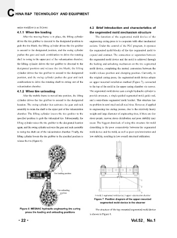
1-mold; 2-segmented mold device; 3-upper vulcanization chamber
Figure 7 Position diagram of the upper-mounted
segmented mold device in the steamer
Figure 6 MESNAC hydraulic engineering tire curing The structure of the top-mounted segmented mold device
press tire loading and unloading positions
is shown in Figure 8.
·22· Vol.52,No.1