
Page 67 - 《橡塑技术与装备》英文版2026年1月
P. 67
PROCESS AND EQUIPMENTS
is of an overall translational type, where the tire grabber group
moves up and down along with the guide rail group driven by
the synchronous gear and rack group. The disadvantage of this
structure of manipulator is that it occupies independent space
and the alignment accuracy is difficult to adjust, resulting in
the raw tire being loaded into the steamer eccentrically, which
requires re-adjustment to the correct position, otherwise it
will affect the vulcanization quality of the tire. However, the 1-Synchronous gear and rack assembly; 2-Guide wheel assembly;
hydraulic engineering tire vulcanizer manipulator developed by 3-Mechanical arm disk; 4-Tire gripper assembly
MESNAC attaches to the moving frame for swinging motion, Figure 4 Original engineering tire curing press robotic
tire grasping component
can move up and down along the column and make circular
motion with the rotating arm, and can also move as a whole installation, saving both time and effort. Another feature is that
with the moving frame in a translational manner. The actions the manipulator's large-span stepless adjustment replaces manual
of tire loading and unloading are highly precise, without the specification adjustment, allowing for a wide range of tire
need for a separate base, saving installation space, achieving specifications and enabling multi-specification replacement.
automatic tire loading and unloading actions, and improving
tire manufacturing quality and work efficiency.
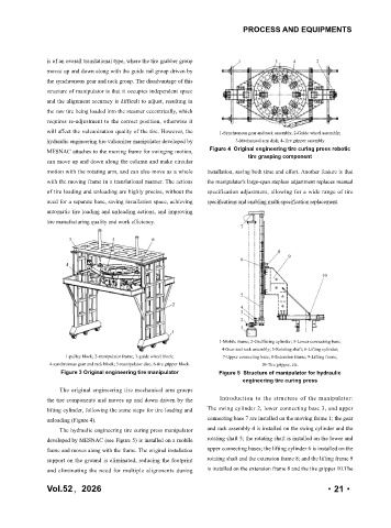
1-Mobile frame; 2-Oscillating cylinder; 3-Lower connecting base;
4-Gear and rack assembly; 5-Rotating shaft; 6-Lifting cylinder;
1-pulley block; 2-manipulator frame; 3-guide wheel block; 7-Upper connecting base; 8-Extension frame; 9-Lifting frame;
4-synchronous gear and rack block; 5-manipulator disc; 6-tire gripper block. 10-Tire gripper, etc.
Figure 3 Original engineering tire manipulator Figure 5 Structure of manipulator for hydraulic
engineering tire curing press
The original engineering tire mechanical arm grasps
the tire components and moves up and down driven by the Introduction to the structure of the manipulator:
lifting cylinder, following the same steps for tire loading and The swing cylinder 2, lower connecting base 3, and upper
unloading (Figure 4). connecting base 7 are installed on the moving frame 1; the gear
The hydraulic engineering tire curing press manipulator and rack assembly 4 is installed on the swing cylinder and the
developed by MESNAC (see Figure 5) is installed on a mobile rotating shaft 5; the rotating shaft is installed on the lower and
frame and moves along with the frame. The original installation upper connecting bases; the lifting cylinder 6 is installed on the
support on the ground is eliminated, reducing the footprint rotating shaft and the extension frame 8; and the lifting frame 9
and eliminating the need for multiple alignments during is installed on the extension frame 8 and the tire gripper 10.The
Vol.52,2026 ·21·